starship ascent cfd simulation
A basic simulation designed to mimic starship ascent at various speeds, altitudes and angles with and without its engines1. Geometry and Grid Generation
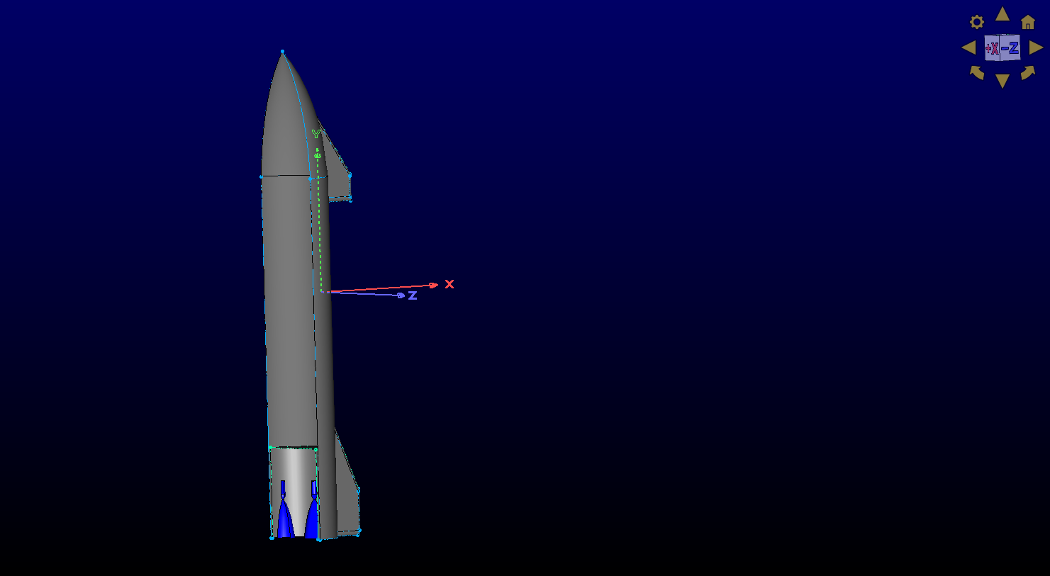
I started by working with a simplified Starship geometry, modeling half of the vehicle using symmetry to reduce computational cost.
Key work:
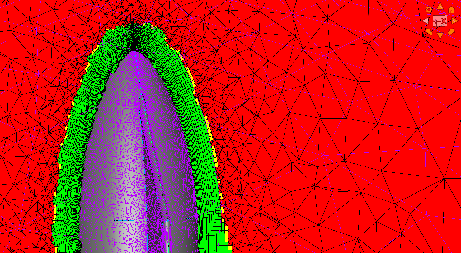
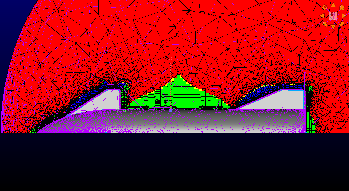
Generated a 3D structured grid using a multi-block (T-Rex) approach
Captured the external flow field around the full vehicle, including control surfaces
Added grid refinement to resolve shock structures (bow shock and expansions)
Kept total cell count under ~1 million while maintaining accuracy
This stage focused on building a high-quality grid capable of resolving compressible flow features without explicitly modeling boundary layers.
2. Flow Solver Setup
The simulation was performed in ANSYS Fluent, modeling compressible, inviscid flow around the vehicle and through the engines.
What I implemented:
Freestream conditions representing ascent trajectory (Mach, altitude, pressure)
Species transport to model realistic air and exhaust gas mixtures
Pressure inlet boundary conditions for the rocket nozzles
Separate cases for:
Thrust OFF (external aerodynamics only)
Thrust ON (fully coupled external + internal flow)
This allowed direct comparison between purely aerodynamic forces and propulsion-influenced flow.
3. Nozzle and Internal Flow Modeling
The internal nozzle flow was approximated using geometry generated from Method of Characteristics principles.
Key features:
Diverging nozzle section with realistic area ratio
Pressure-driven inflow conditions to simulate combustion chamber output
Tracking of exhaust species through the nozzle and into the external flow
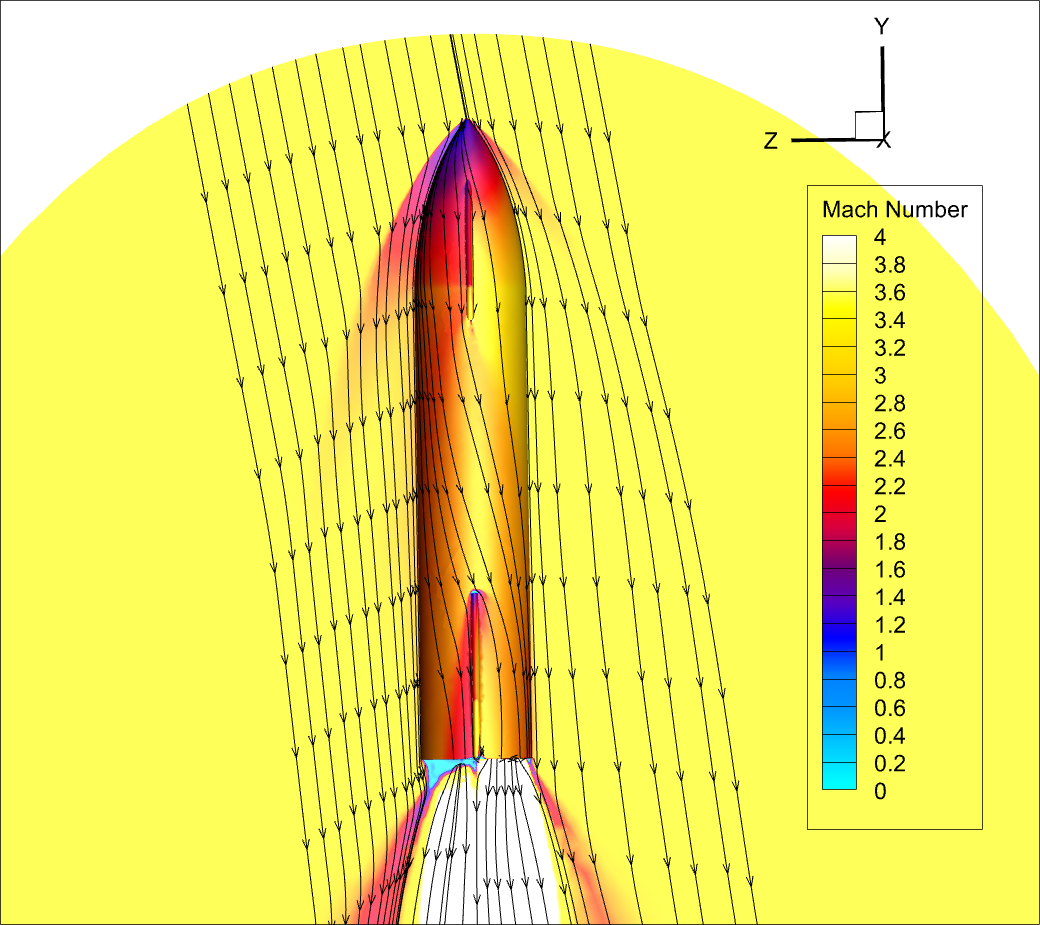
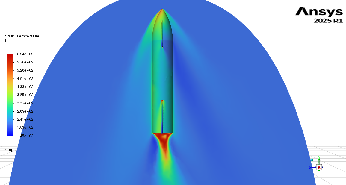
This enabled analysis of how the exhaust plume interacts with the surrounding flow field.
4. Grid Adaptation and Shock Resolution
To improve accuracy, I applied grid adaptation based on pressure gradients.
Refined regions with strong curvature (shock locations)
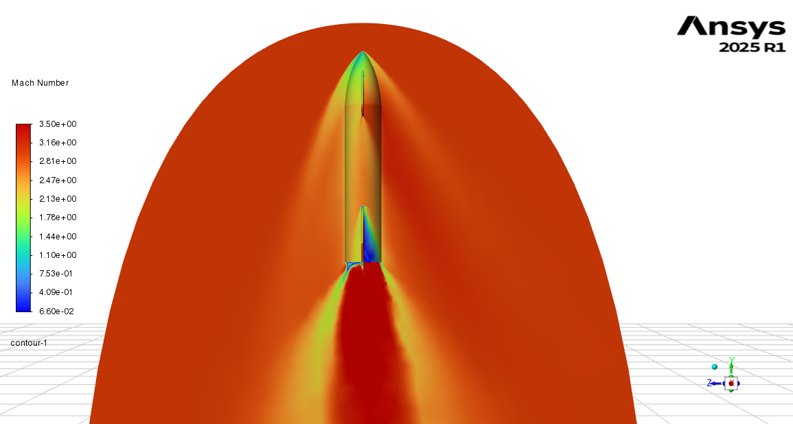
Improved resolution of bow shocks and plume structures
Ensured stable and converged solutions for both cases
This step was important for accurately capturing high-speed compressible flow features.
5. Performance Analysis
From the simulations, I extracted key aerodynamic and propulsion metrics:
Drag, lift, and pitching moment coefficients
Force and moment distributions across the vehicle
Thrust generated by integrating pressure forces inside the nozzle
Comparison between thrust-on and thrust-off cases
This provided a complete picture of how propulsion affects vehicle aerodynamics during ascent.