Liquid Flight Vehicle Tank Sizer
This project started as a way for me to understand how pressure vessels worked and to improve on my coding ability. Whilst it is still a work in progress it has provided myself and my club with an adaptable and completely parametric tank designer that updates CAD files to streamline the design progress significantly.Overview
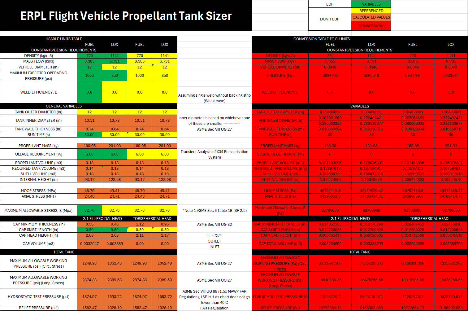
The first iteration of this sizer was done in Excel as I wanted a program I knew well and could fix quickly after I inevitably made mistakes but also as it was significantly easier to see everything work together unlike a program script such as Python or MATLAB. Finally, as this was for my club I wanted anyone to be able to understand what was going on hence the use of Excel.
The file takes 8 inputs from the user which include propellant density, mass flow rates, vehicle diameter, maximum expected operating pressure (MEOP), weld efficiency, run time, ullage requirement and material maximum allowable stress which provided all necessary parameters to create the required geometries.
All dimensions were calculated with strict adherence to the ASME Boiler and Pressure Vessel Code to ensure safety for all those involved once the tanks are in use. Section 8 was the most applicable to this application and is referenced repeatedly in the file so anyone can understand where the equations came from. Furthermore, the relief and hydrostatic pressure values were provided by the Friends of Amateur Rocketry (FAR) as design requirements as part of the dollar per foot challenge.
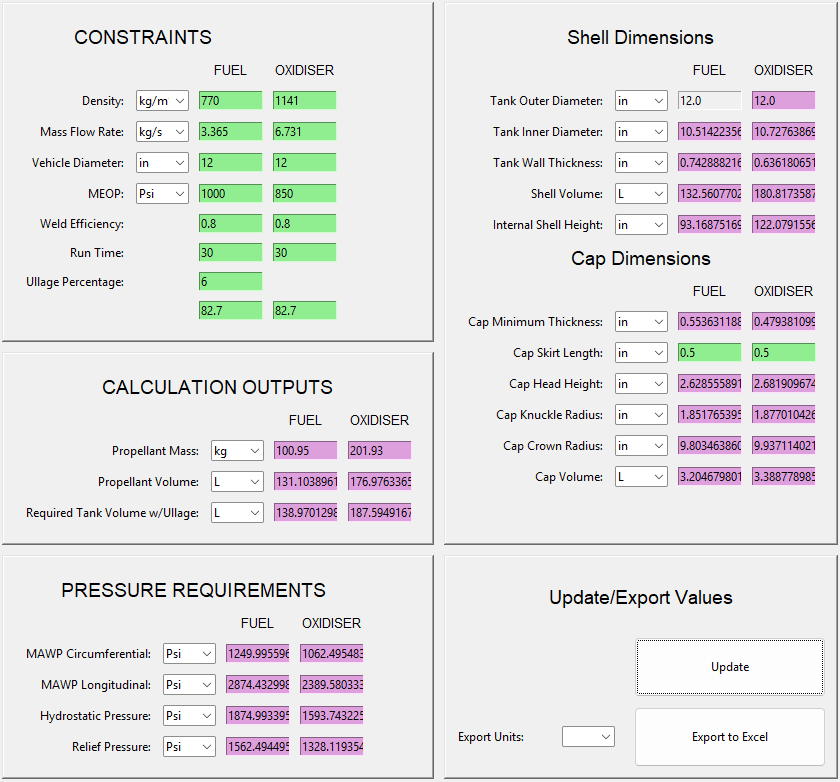
Once I had the Excel sizer complete and I was happy with it I moved on to start recreating it as an interactive GUI in Python. I chose this to help myself gain a better understanding of Python as my use of the program had been limited up to this point. My main goal however was not only to allow users to see the values they needed but also to update in real time to Autodesk Inventor which would allow for rapid design iterations. This also helped me gain a better understanding of parametric modelling in Inventor.
For updating the CAD in inventor, the GUI exports certain parameters into an Excel sheet which is linked to an Inventor assembly with associated sub parts such as the cylindrical section and the caps. When the "Export to Excel" button is pressed the Excel file is created or updated which inventor reads almost instantaneously.
Whilst the main sizing is done this project is still a work in progress to add smaller quality of life changes and design capabilities.
ASME Specifications
I previously reference ASME BPVC section 8 that was used for many of the sizing calculations but below are the other specifications I used and why:
ASME BPVC Section VIII
UG 27 - Used to find the shell's minimum wall thickness based on our internal pressure
UG 32 - Used to find the caps/heads minimum wall thickness if using formed heads (not machined heads)
UG 99 - Provided guidelines for hydrostatic pressure testing, however Friends of Amateur Rocketry has higher required safety factors (1.5x MAWP) which overruled the 1.3x MAWP specified by ASME.
ASME BPVC Section II
Used Table 1B to find the Maximum Allowable Stress value for chosen material
Intial excel sizer
Python gui
My files
If you wish to have a look at these yourself the Excel file and the Python GUI with the CAD files can be found at my GitHub which is linked below.